User Tools
Site Tools
12big Rack Serial 2
User Manuals Print page
 Save page as PDF
Table of Contents


Table of Contents
Installation
Introduction
In this chapter, you are shown how to plan and install your LaCie 12big Rack Serial 2 into an industry standard 19 inch rack cabinet.
Caution: When connecting up the LaCie 12big Rack Serial 2, use only the power cords supplied or cords which match the specification quoted in AC Power Cords.
Planning Your Installation
Before you begin installation you should become familiar with the configuration requirements of your LaCie 12big Rack Serial 2. The correct locations of each of the plug-in modules are shown in Figure 3-1.
Important info: Installation procedures should be performed by Service Personnel Only.

Enclosure Installation Pre-Requisites
LaCie 12big Rack Serial 2 enclosures are supplied and delivered fully populated with drive carrier modules pre-installed.
Caution: The LaCie 12big Rack Serial 2 Enclosure with all its component parts installed is too heavy for a single person to easily install into a rack cabinet.
Ensure that you have fitted and checked a suitable anti-static wrist or ankle strap and observe all conventional ESD precautions when handling LaCie 12big Rack Serial 2 modules and components. Avoid contact with Midplane, Motherboard and module connectors, etc.
Ensure that you have fitted and checked a suitable anti-static wrist or ankle strap and observe all conventional ESD precautions when handling LaCie 12big Rack Serial 2 modules and components. Avoid contact with Midplane, Motherboard and module connectors, etc.
Critical pre-requisite requirements and good handling practices are highlighted in the following installation procedures. We encourage you to follow these procedures to ensure that a successful installation is achieved in the easiest manner.
Preparation of Site and Host Server
Before you begin, make sure that the site where you intend to set up and use your LaCie 12big Rack Serial 2 storage system has the following:
- Standard AC power from an independent source or a rack Power Distribution Unit with a UPS (Universal Power Supply).
- Host computer with the correct software, BIOS and drives. contact your supplier for the correct software levels.
- Before setting up your enclosure ensure you have the following:
- SAS HBA
- Mini-SAS to Host Cable
- Power Cord
- Rail Kit (if installing within a rack)
Please refer to your supplier for a list of qualified accessories for use with the enclosure. The Accessories Box contains the power cords and other accessories.
Unpacking the Enclosure System
- Inspect the packaging for crushes, cuts, water damage or any other evidence of mishandling during transit. If any damage appears present, for future reference, photograph the packaging before opening.
- The unpacking procedure is shown in Figure 3-2.

Planning and Configuring Your Installation
Before you begin installation you should become familiar with the configuration requirements of your LaCie 12big Rack Serial 2. Please refer to Planning Your Installation for information on your overall system configurations.
When planning your system configuration, please remember that all LaCie 12big Rack Serial 2 enclosure drive bays must be filled with a Drive Carrier Module or a Dummy Drive Carrier Module, no bays should be left completely empty.
Special Tools and Equipment
There are no special tools required but in order to complete the assembly of some configurations you may need the following (not supplied):
- Flat blade screwdriver
- Torx driver (for drive module locks)
Rack Installation Pre-Requisites
The LaCie 12big Rack Serial 2 Enclosure is designed for installation into an industry standard 19 inch cabinet capable of holding such enclosures.
- Minimum depth 707mm (27.83 inches) from rack posts to maximum extremity of enclosure (excludes rear cabling).
- Weight: up to 26kg (57lb), dependent upon configuration, per enclosure.
- A minimum gap of 25mm (1inch) clearance between the rack cover and front of drawer; and 50mm (2 inches) rear clearance between rear of drawer and rear of rack is recommended in order to maintain the correct air flow around the enclosure.
- The rack should present a maximum back pressure of 5 pascals (0.5mm water gauge).
Caution: Operation of the LaCie 12big Rack Serial 2 with ANY modules missing will disrupt the airflow and the drives will not receive sufficient cooling. It is ESSENTIAL that all apertures are populated before operating the enclosure system. Dummy Drive Carriers and Blank Modules are available for this purpose.
Rack Mounting Rail Kit
A set of rack mounting rails is available for use in 19 inch rack cabinets. These rails have been designed and tested to handle the maximum enclosure weight and to ensure that multiple enclosures may be installed without loss of space within the rack. Use of other mounting hardware may cause some loss of rack space.
Please contact your supplier to ensure suitable mount rails are available for the rack you are using.
Enclosure Installation
- Remove the Rack Mounting Rail Kit from the Accessories Box and check for damage.
- Attach left and right chassis slides to the enclosure sides using 8 M3 x 4 buttonhead screws (see Figure 3-3).
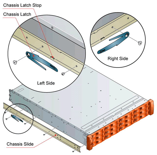 Figure 3-3 - Securing Chassis Slides to Enclosure
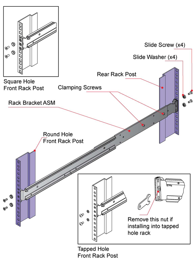 Figure 3-4 - Securing Brackets to Rail
 - Assemble the left and right chassis latches using the special chassis latch screws. Ensure the latch is orientated as shown in Figure 3-12, with the spring arm located against its stop. On the right hand side this is at the top, on the left at the bottom.
- Assemble the rack brackets to the rack posts as follows (see Figure 3-13):
- Position the location pin at the rear of the rail into a rear rack post hole. Attach the bracket to the rear rack post using the washers and screws supplied. The screws should be left loose.
- Extend rail to fit between the front and rear rack posts.
- Attach the bracket to the front rack post using the washers and screws supplied. The screws should be left loose.
- Tighten the two clamping screws located along the inside of the rear section of the rack bracket.
- Mount the enclosure into the rack as follows:
- Lift the enclosure and align it with the rack rails.
- Carefully insert the chassis slides into the rack rails and push fully home.
- Tighten the rear rack bracket mounting screws.
- Withdraw enclosure until it reaches the hard stops (approximately 400mm) and tighten the front rack bracket mounting screws.
- Return the enclosure to the fully home position.


Module Installation
LaCie 12big Rack Serial 2 enclosures are supplied and delivered populated with Midplane PCB and all plug-in modules installed. For information on removal/replacement of plug-in modules, please refer to Troubleshooting and Problem Solving.
Dummy Drive Carrier Modules
Dummy Drive Carrier Modules must be fitted in all unused drive bays to maintain a balanced airflow.
Blank Modules
Blank PCM or I/O Modules must be fitted in any vacant I/O Module bays respectively at the rear of the enclosure to maintain airflow and ensure correct operation.
Important info: Operation of the LaCie 12big Rack Serial 2 with ANY modules missing will disrupt the airflow and the drives will not receive sufficient cooling.
Power Cord Connection
Parts Check List
- Power cords to requisite local standards.
Procedure
- Connect the power cord(s) to the Power Distribution Unit(s) (PDUs) (see Figure 3-6).
Important info: When more than one PCM is fitted, to ensure redundancy all power cords must be connected to separate and independent supplies.

Caution: The power connections must always be disconnected prior to removal of the Power Cooling Module from the enclosure.
When bifurcated power cords (“Y” leads) are used, these cords must only be connected to a supply range of 200-240 VAC.
When bifurcated power cords (“Y” leads) are used, these cords must only be connected to a supply range of 200-240 VAC.
System Configurations
The basic configuration is a single LaCie 12big Rack Serial 2 enclosure connected to a single Host Bus Adaptor (HBA).
Important info: Connections can be made up to a maximum of 8 enclosures.
Before setting up your enclosure please ensure that you have the following:
- SAS HBA
- Mini-SAS to Host Cable
- Power Cable
- Rack Mounting Rail Kit (if installing within a rack)
Please refer to your supplier for a list of qualified accessories for use with LaCie 12big Rack Serial 2 enclosures. Multiple enclosures may be connected together using SAS patch cables, up to a maximum of 4 enclosures. There are three main expansion configurations:
- Single Host, Single Connection, shown in Figure 3-7
- Single SBB module
- Supports SAS or SATA drives
- Expansion up to 96 drives
- Dual Host, Single Connection
- Dual SBB module
- Supports SAS or SATA drives (with dongle)
- Expansion up to 96 drives
- Dual Host, Dual Connection, shown in Figure 3-8
- Dual SBB module
- Supports SAS or SATA drives (with dongle)
- Expansion up to 96 drives


Important info: In order to use the 12big Rack Serial 2 as an expansion to the 12big Rack Network, internal firmware needs to be updated. On the included CD, run “UpgradeSerial2ForNetwork.bat” located in the Applications folder. This batch file will update firmware on up to three expansions connected to the RAID controller. Please wait until the process is finished and all chassis have rebooted.
During this process, you may receive one or several “Event Notification Application” errors. Simply acknowledge the errors by clicking OK. They are due to the flashing process and enclosure reboot and have no effect on the status of the host connection.
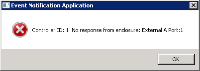
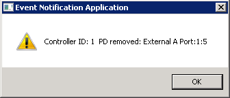
During this process, you may receive one or several “Event Notification Application” errors. Simply acknowledge the errors by clicking OK. They are due to the flashing process and enclosure reboot and have no effect on the status of the host connection.


Grounding Checks
The product must only be connected to a power source that has a safety electrical earth connection.
The earth connection to the rack must be checked before switching on, by an electrical engineer who is qualified to the appropriate local and National standards to perform the check.
Data Security
- Power down your host computer and all attached peripheral devices before beginning installation.
- Each enclosure contains up to 12 removable disk drive modules. Disk drives are fragile. Handle them with care, and keep them away from strong magnetic fields.
- All the supplied plug-in modules must be in place for the air to flow correctly around the enclosure and also to complete the internal circuitry.
- If the enclosure system is used with modules missing for more than a few minutes, the enclosure can overheat, causing power failure and data loss. Such use may also invalidate the warranty.
- If you remove a drive module, replace it immediately. If it is faulty, replace it with a drive module of the same type and capacity.
- Ensure that all disk drives are removed from the enclosure before attempting to manhandle or move the rack installation.
- Do not abandon your backup routines.
© LaCie 2024
Last modified : Mar 01, 2013