User Tools
Site Tools
Table of Contents
Operation
Before You Begin
Before powering up your LaCie 12big Rack Serial 2 please ensure that all the modules are firmly seated in their correct bays.
Power On
Follow the procedure below to Power On the enclosure.
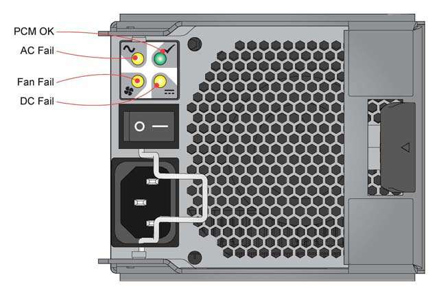
- Power On the system by connecting the power cables to the PDU and moving the PCM switch (Figure 4-1) to the ON position
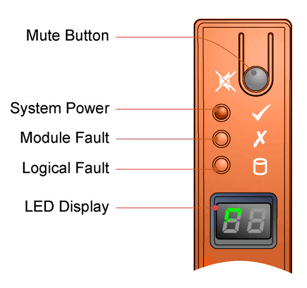
- The System Power LED on the Ops Panel should be lit (Green) when the enclosure power is activated (and the disk drive motors should start).
Power Cooling Module LEDs
The PCM incorporates the following LEDs:
| PSU OK: | Green |
| AC Input Fail: | Amber |
| Fan Fail: | Amber |
| DC Output Fail: | Amber |
PCM LEDs and switches are shown in Figure 4-1.
Ops Panel LEDs
The Ops Panel LEDs fault and status conditions are described in Table 4-1 and shown in Figure 4-2. Please refer to Table 5-2 for details of any fault indication.
Table 4-1: Ops Panel LEDs
| LEDs | Status |
| System Power | Constant Green: good or positive indication Constant Amber: fault present |
| Module Fault | Constant or Flashing Amber: fault present |
| Logical Fault | Constant or Flashing Amber: fault present |
Setting the Unit Identification Number
First Set
At first system power on, the Unit Identification Number is not set. The enclosure management system will recognize this and set the display to “00” and flash the digits at 1Hz. The system will delay power up until the Unit Identification Number is set.
- To set the number, press and hold the Mute switch, which will stop the first digit (left hand digit) flashing and start incrementing the number by 1 every 2 seconds. When the first required number is reached, release the switch for 5 seconds, at which point the first number is locked and the second number may be set.
- To change the second digit (right hand digit), press and hold the switch again to achieve the desired number, otherwise if there is no action for 5 seconds the enclosure management system will select “0”.
The values “01” to “99” will be valid. Value “00” is reserved and will cause the system to interrupt the power up until set.
The value “00” will be the default Power On value. Once an enclosure Unit Identification Number is set, it will be stored in the midplane VPD by the Enclosure Management software. On future power cycles, midplane logic will initially set “00” on the display whilst the enclosure management software reads the setting from the VPD. Software will then set the display to the correct value, or halt boot if it is not set or “00”. In a situation where there is no enclosure management (no I/O modules, or single module with management failure) the enclosure will display “00”.
Re-set
Re-setting the number is similar to the first set above, with the exception that the user must press and hold the switch for 5 seconds in the first instance to enter the setting mode. On entering this mode the display will flash the current Unit Identification Number setting. A single press (<2 seconds) of the Mute switch will retain the existing setting without increment. The enclosure will ONLY accept the new Unit Identification Number following an Enclosure Power Cycle, hence if the number set on the display is DIFFERENT from that loaded at Start of Day the enclosure will flash both the Module Fault LED and the Logical Status LED, and set alarm state S1 until the enclosure is power cycled.
Software/SES
The enclosure Unit Identification Number may be read and set via CLI and SES. As above, the new setting will only be applied after a power cycle. All other functionality shall remain the same as described above.
Starting the Drives
Unless otherwise selected during installation, all drives in the enclosure should automatically start their motors. If this has not occurred one of the following conditions may exist:
- There may be a power problem (an alarm and power fault indication would normally be active).
- If there is only one PCM present in a 12 drive enclosure, the drive motors will spin up in a delayed sequence.
Disk Drive LEDs
Each Drive Carrier Module incorporates two LEDs, Upper (Green) and Lower (Amber), shown in Figure 2-9.
- In normal operation the Green LED will be ON and will flicker as the drive operates
- In normal operation the Amber LED state will be:
- OFF if there is no drive present,
- OFF as the drive operates, and
- ON if there is a drive fault present.
Engaging the Drive Module Anti-tamper Locks
The anti-tamper locks are fitted in the drive carrier handles and are accessed through the small cutout in the latch section of the handle.
Activating the Locks
- Carefully insert the lock key provided into the cutout in the handle.
- Locate the key into its socket.
- Rotate the key in a clockwise direction until the indicator is visible in the aperture beside the key.
- Remove the key.
De-activation is the reverse of this procedure, that is:
Rotate the key in an anti-clockwise direction until the indicator is no longer visible in the aperture beside the key.
Power Down
To power the enclosure system down, either switch off the Power Cooling Module(s) installed in the enclosure by moving the PCM switch (Figure 4-1) to the OFF position. or remove AC mains at the power source.

 Print page
 Save page as PDF


