User Tools
Site Tools
12big Rack Serial 2
User Manuals Print page
 Save page as PDF
Table of Contents


Table of Contents
Module Removal and Replacement
Overview
The LaCie 12big Rack Serial 2 includes an Enclosure Services Processor and associated monitoring and control logic to enable it to diagnose problems within the enclosure’s power, cooling and drive systems.
Caution: Whenever replacing a module NEVER leave an EMPTY bay in the rear of the enclosure, obtain a replacement or blank module before removing the problem part.
ESD Precautions
Caution: It is recommended that you fit and check a suitable anti-static wrist or ankle strap and observe all conventional ESD precautions when handling LaCie 12big Rack Serial 2 plug-in modules and components. Avoid contact with Midplane components and module connectors, etc.
Replacing Power Cooling Modules
Note: The Power Cooling Module (PCM) is hot-swappable and therefore removal/replacement may be performed by the user.
Caution: Do not remove covers from the PCM. Danger of electric shock inside. Return the PCM to your supplier for repair.
Removing a Power Cooling Module
Caution: Prior to removing the PCM, please disconnect the power from the PCM, by either the mains switch (where present) or by physically removing the power source in order to ensure that your system has warning of an imminent power shutdown. A faulty PCM must be replaced by a fully operational PCM within 24 hours.
- Ensure that you identify the faulty PCM correctly.
- Switch off and disconnect the power supply cord.
- Grasp the latch and the side of the PCM handle between thumb and forefinger, squeeze together and open the handle to cam the PCM out of the enclosure (see Figure 6-1).
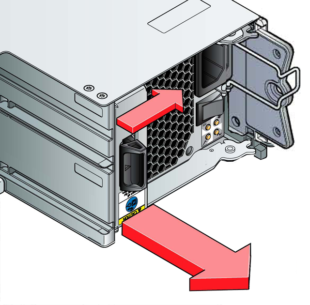 Figure 6-1 - Removing a PCM (1)
- Grip the handle and withdraw the PCM. (Figure 6-2).
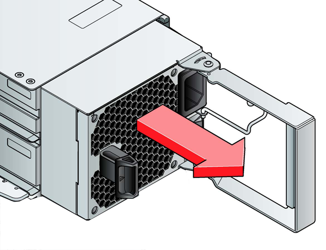 Figure 6-2 - Removing a PCM (2)


Installing a Power Cooling Module
Parts Check List
- 580W AC PCM
Important info: Operation of the enclosure with ANY modules missing will disrupt the airflow and the drives will not receive sufficient cooling. It is ESSENTIAL that all apertures are filled before operating the enclosure system.
Caution: Do not remove covers from the PCMs. Danger of electric shock inside. Return the PCM to your supplier for repair.
Handle the PCM carefully and avoid damaging the connector pins. Do not install the PCM if any pins appear to be bent.
Handle the PCM carefully and avoid damaging the connector pins. Do not install the PCM if any pins appear to be bent.
- Check for damage, especially to all connectors.
- With the PCM handle in the open position, slide the module into the enclosure (Figure 6-3).
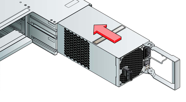 Figure 6-3 - Installing a PCM (1)
 - Cam the module home by manually closing the PCM handle. A click should be heard as the handle latch engages (see Figure 6-4).
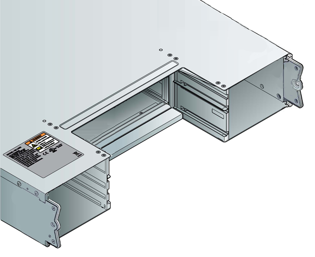 Figure 6-4 - Installing a PCM (2)
 - Connect the power cables to the power source and to the PCM.
- Secure the strain relief bales.


Replacing Drive Carrier Modules
Caution: Observe all conventional ESD precautions when handling LaCie 12big Rack Serial 2 modules and components. Avoid contact with Midplane components and module connectors, etc.
Removing a Drive Carrier Module
Drive spin down: Damage can occur to a drive if it is removed while still spinning. If possible use the operating system to spin down the drives prior to removal. If this is not possible we recommend that you perform ALL steps of the following procedure to ensure that the drive has stopped prior to removal.
- If the anti-tamper lock has been activated, de-activate by locating the key into its socket and rotating it in an anti-clockwise direction until the indicator is no longer visible in the aperture beside the key.
- Release the carrier handle, by pressing the latch in the handle towards the handle hinge (i.e. towards the front of the enclosure), see Figure 6-5).
- Gently withdraw the Drive Carrier Module approximately 1 inch (25mm), and wait 30 seconds (see Figure 6-6).
- Withdraw the module from the drive bay.
Caution: Dummy Drive Carrier Modules MUST be fitted to ALL unused drive bays.There will be inadequate drive cooling if any are left open.


Installing a Drive Carrier Module
Important info: A Drive Carrier Module cannot be installed if its anti-tamper lock is activated outside the enclosure. Please refer to Removing a Drive Carrier Module for the de-activation procedure.
Parts Check List
- 3.5” Drive Carrier Module
- Release the drive carrier handle, by depressing the latch in the handle (see Figure 6-7).
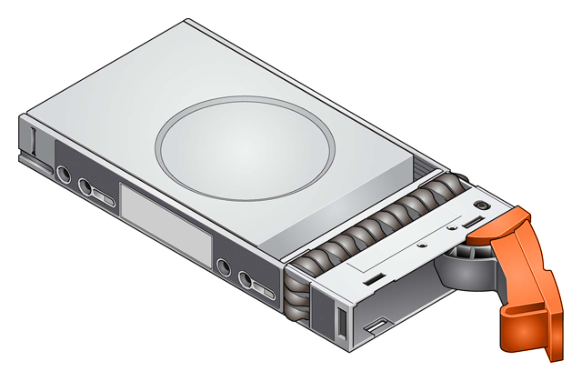 Figure 6-7 - Installing a Drive Carrier Module (1)
 - Insert the Drive Carrier Module into the enclosure (Figure 6-8). Important: Ensure that the drive carrier is orientated so that the drive is uppermost and the handle opens from the left, as shown in Figure 6-8.
- Slide the drive carrier, gently, all the way into the enclosure.
- Cam the drive carrier home - the camming foot on the base of the carrier will engage into a slot in the enclosure. Continue to push firmly until the handle fully engages. A click should be heard as the latch engages and holds the handle closed.

Caution: Ensure that all drive carriers are fully engaged in the enclosure by firmly pushing each one home into the slot, as shown in Figure 6-9.


Activating the Anti-tamper Locks
- Carefully insert the lock key provided into the cutout in the handle.
- Locate the key into its socket.
- Rotate the key in a clockwise direction until the indicator is visible in the aperture beside the key.
- Remove the key.

Dummy Carrier Module Removal/Replacement
Dummy Drive Carrier Modules are removed and replaced in the enclosure simply by pulling the module out of the enclosure or pushing it into place.
Replacing I/O Modules
Note: The I/O Module is hot-swappable and therefore removal/replacement may be performed by the user.
Important info: This section provides only general guidelines on I/O Module replacement, please refer to the SBB I/O Module Installation Guide (P/N xxxxx-01) for more detailed procedures. However, the information included here is adequate for the fitting of Blank I/O Modules.
Caution: Blank I/O Modules MUST be fitted in all unused slots, there will be inadequate enclosure cooling if the slot is left open.
Removing an I/O Module
Caution: Do not remove this module unless a replacement can be immediately added. The system must not be run without all modules in place.
- Grasp the module latch between the thumb and forefinger and squeeze them together to release the latch.
- Pull the latch outward to cam the module out of the enclosure (Figure 6-11).
- Grip the latch handles and withdraw the module (Figure 6-12).


Installing an I/O Module
Caution: EMC Precautions: If passive copper cables are connected, the cable must not have a connection to a common ground/earth point.
- Check for damage, especially to the interface connector - do not install if the pins are bent.
- With the latches in the open position (see Figure 6-13), slide the module into the enclosure until the latches engage automatically.
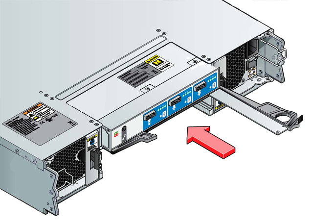 Figure 6-13 - Installing an I/O Module
 - Cam the module home by manually closing the latches.
- A click should be heard as the latches engage.

Note: The I/O module will take up to 1 minute to re-initialize after re-cabling.
© LaCie 2024
Last modified : Mar 01, 2013