User Tools
Site Tools
Table of Contents
System Overview
LaCie 12big Rack Serial 2 Enclosure
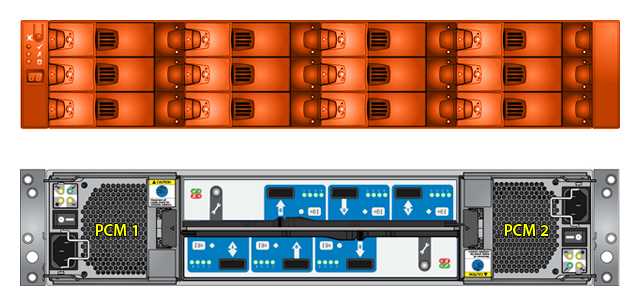
The LaCie 12big Rack Serial 2 design concept is based on an enclosure subsystem together with a set of plug-in modules. A typical enclosure system (as supplied) comprises:
- An Enclosure Chassis comprising:
- A Midplane PCB
- An integral, front flange mounted Operator’s (Ops) Panel
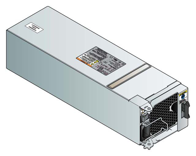
- Up to two 580W, 100-240V AC Power Cooling Modules (PCMs), (see Figure 2–4)
- Up to two SBB compliant I/0 modules
- Up to 12 Drive Carrier Modules with drives installed.
- Rail Kit for rack mounting.
Enclosure Chassis
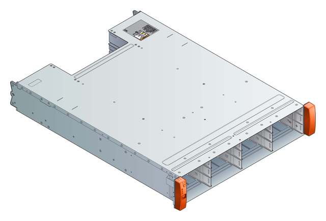
The Chassis consists of a sheet metal enclosure assembly containing an integrated Midplane PCB and module runner system.
- The chassis is fitted with 19 inch Rack mounting features which enables it to be fitted to standard 19 inch racks and uses 2 EIA units of rack space (i.e. 3.5” high).
- The Midplane PCB provides up to 12 x 3Gb/s SAS Drive connections (SFF8482).
- There are up to 12 drive bays at the front of the enclosure, in horizontal orientation. Each drive bay accommodates a plug-in Drive Carrier Module which can house 12 x 3.5-inch form factor drives horizontally.
- At the rear, the chassis assembly accommodates up to 2 PCMs and up to 2 SBB Modules.
Operator (Ops) Panel
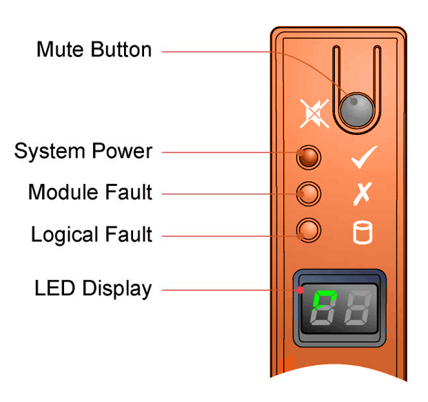
The enclosure front panel incorporates an Operator’s (Ops) Panel, shown in Figure 2–3, housed on the left hand mounting flange and connected to the Midplane via a flexible cable. The Ops Panel is a passive component, controlled from the midplane and with all its functions driven from the I/O modules.
This assembly provides the following functions:
- Mute/Input Button
- System Power LED (Green/Amber)
- Module Fault LED (Amber)
- Logical Status LED (Amber)
- Unit Identification LED Display (dual 7 segment LED display)
- Audible Alarm
- Thermal Sensor
Mute/Input Button
Used in the setting of the Unit Identification display. Also used to transition Alarm state S1 to Alarm state S2/S3 depending on VPD setup (please refer to Table 5–5 for details of the alarm states).
System Power On/Standby LED (Green/Amber)
This LED shows Amber when Standby Power ONLY is available. It is Green when system power is available.
Module Fault LED (Amber)
The module fault LED is illuminated when there is a system hardware fault. It may be associated with a fault LED on a PCM or I/O Module which helps the user to identify the component that has a fault.
Logical Status LED (Amber)
The Logical Status LED provides indication of a change of status or fault from something other than the Enclosure Management (EM) system. This may be from an Internal or External RAID controller or HBA and communicated to the enclosure (normally via SES). It is usually associated with a disk drive and LEDs at each disk drive position helps the user to identify the drive affected.
Unit Identification Display
The Unit Identification Display is a dual seven segment display that can be used to provide feedback to the user. Its primary usage is to display an Enclosure Unit Identification Number to assist users in setting up and maintaining multiple enclosure systems.
The Unit Identification Display is configured via a VPD option. By default the display will be OFF, and the dual seven segment display will be OFF. If the VPD selects use of the display, the seven segment display will be ON and display the number stored in VPD.
Audible Alarm
Audible alarm which is activated by the LaCie 12big Rack Serial 2 firmware for a variety of situations. Please refer to Troubleshooting for more information.
Thermal Sensor
The ambient thermal sensor provides input to the enclosure about the external operating ambient temperature. This device is a remote sensor to a thermal sensor mounted on the enclosure midplane. It also provides presence detection for the Ops Panel.
Power Cooling Module
AC-DC Power is provided by up to four commercial 580 W auto-ranging Power Cooling Modules (PCMs) with integrated axial cooling fans, up to 2 in each module. Fan speed is controlled from the SBB I/O Modules.The system airflow is described in System Airflow.
PCM voltage operating ranges are nominally 100V - 240V AC. A typical PCM is shown in Figure 2–4. Each PCM incorporates an AC mains power input switch and the following status indicators:
- Power LED (Green)
- AC Fail LED (Amber)
- PCM Fail LED (Amber)
- AMD Fail LED (Amber)
Cooling Module
The Power Cooling Module has been designed such that the PCM element is separate from the Cooling control and status element. Therefore, the same module can be used for a Cooling only module if the PCM element is not fitted inside the PCM canister.
Multiple PCMs
The LaCie 12big Rack Serial 2 includes two PCMs in an enclosure. Multiple PCMs provide redundant power control for the system so that if one PCM fails the other(s) maintains the power supply and enclosure operation is not affected while you replace the faulty module.
PCMs are hot-pluggable and replacement should only take a few minutes to perform but must be completed within 10 minutes from removal of the failed PCM.
System Airflow
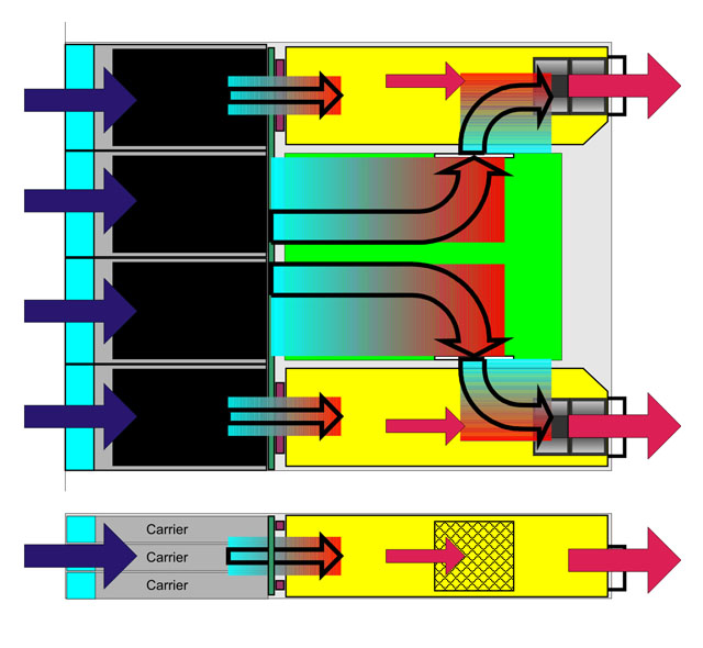
The system airflow is from the front to the rear of the enclosure, shown below.
- Cooling airflow passes between drives and through, over and under the Multiplan to the central plenum.
- The PCMs pull air from the plenum and from the I/O Module.
- Airflow exits at the rear of the power/cooling module.
The system must be operated with low pressure rear exhaust installation.(Back pressure created by rack doors and obstacles not to exceed 5 pascals (0.5mm Water gauge)). The cooling system provides sufficient capacity to ensure that drive maximum temperatures (shown below) are not exceeded:
- Up to 200W combined I/O Module power:
- 40°C ambient with one Fan failed at 7,000 ft.
- 35°C ambient with one Fan failed at 10,000 ft.
- Up to 400W combined I/O Module power:
- 35°C ambient at 7,000 ft.
- 30°C ambient at 10,000 ft.
SBB I/O Module
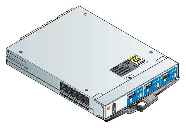
LaCie 12big Rack Serial 2 enclosure systems include up to 2 x I/O Modules: 2 x SBB compliant Interface Slots. Blank modules must be fitted in all unused SBB slots.
The SBB modules are mechanically and electrically compliant to the latest SBB V2 specification.
The system can operate from one module with a module blank providing airflow control in the other slot, or from two modules. Module presence are checked against the start of day configuration to determine invalid configuration conditions.
Each SBB I/O Module includes an EEPROM connected to the SBB I2C bus that contains VPD data describing the function and capability of the SBB module. In this way the SBB modules can discover the type and capabilities of the partner SBB module(s) and vice versa within the enclosure. Incompatible configurations will result in an enclosure system alarm.
I/O Module LEDs
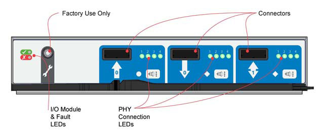
Each I/O module, (Interface or Auxiliary slot), has the following LEDs on the rear faceplate:
- Fault (Amber) to indicate a faulty module. This LED is driven either from a failure detected within the faulty module or by a fault detected by its partner module via cross-over connection provided by the Midplane.
- I/O Module: Green when OK, flashing green indicates a VPD error.
- Host Port Activity: Green Activity, flashing green indicates No Activity
Blank I/O Modules
Blank I/O Modules are provided and must be fitted in any vacant I/O module bay at the rear of the enclosure to maintain airflow and ensure correct operation.
Drive Carrier Module
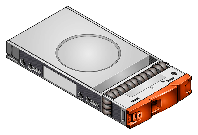
The Drive Carrier Module comprises a hard disk mounted in a carrier.
Each drive bay will house a single Low Profile 1.0 inch high, 3.5 inch form factor disk drive in its carrier. Drives are fitted horizontally.
Each disk drive is enclosed in a sheet steel carrier which provides excellent thermal conduction, radio frequency and electro-magnetic induction protection and affords the drive maximum physical protection.
The front cap also supports an ergonomic handle which provides the following functions:
- Camming of carrier into and out of drive bays.
- Positive ‘spring loading' of the drive/Midplane connector.
The carrier supports the following interfaces:
- Dual path direct dock Serial Attached SCSI, or
- Dual path SATA via a carrier mounted Transition Card.
Drive Status Indicators
Disk drive status is monitored by a Green LED and an Amber LED mounted on the front of each Drive Carrier Module, under ESI processor control, shown in Figure 2–9. Please refer to Drive Carrier Module LEDs for a description of the LED states.
Anti-tamper Locks
Anti-tamper locks are fitted in the drive carrier handles (Figure 2–9) and are accessed through the small cutout in the latch section of the handle.These are provided to disable the normal 'pinch' latch action of the carrier handle.
Transition Card
The carrier supports a Transition Card positioned between the drive and the Midplane and mounted in the drive carrier. It is mounted vertically in drive carriers.
For Serial ATA use, a Transition Card is attached to the rear of each drive with a SATA connector. A SAS connector is provided for insertion of the drive assembly into the Midplane. Dual path operation of SATA drives is accomplished via an active-active multiplexer device on the Transition Card.
The Transition Card has the following features:
- SAS(STP) to SATA interface
- Active/Active Port selection
- Industry standard SAS connector
- Hot plug support with current inrush limiting (Drive Power Control)
- Proven robust connector interface for multiple insert/extract cycles.
- Upgrade path to Drive Power Control on MicroDongle
Dummy Drive Carrier Modules
Dummy Drive Carrier Modules are provided for fitting in all unused drive bays. They are designed as integral drive module front caps with handles and must be fitted to all unused drive bays to maintain a balanced airflow.
Enclosure Management
The Enclosure is actively managed by the various SBB I/O Modules. Management is performed by the modules in the Interface card slots as these have all the required connections. Each module may contain a SAS expander with associated Enclosure Management Processor (ESI). ESI is also referred to as Storage Enclosure Processor (SEP).
If there is an SBB I/O Module and an Auxiliary I/O Module then the enclosure management may be via SES from the Auxiliary module to an SES target on the SBB I/O Module in the Interface Card slot.
The SEP housed in the SBB modules will interface to the enclosure through dedicated control lines, SGPIO or I2C to the components of the enclosure. The SEP will provide information using SCSI Enclosure Services (SES) ANSI standard through a SES target in a host SAS expander, or alternatively by another target device, dependent upon the module type in use. Note that each IO module contains independent SES targets. If one of the SES targets fails, the other will continue to function.
SES control and monitoring of other functions of the specific interface module type installed will vary according to functions provided and can be found in the module specification or the SES Interface specification appropriate to that module type.

 Print page
 Save page as PDF


